The world of electricity right at their fingertips!
Watch and learn with your child as they discover how electricity works through a series of fun and educational projects using our Circuit Scribe products. Coach your child through the project by using the provided tutorials instructions and soon they will be on their way to learning the basics of electricity!
Flashing Fire Truck
Step One

The Blinker Module
In the world around us a lot of things happen automatically. Maybe you’ve seen a door that opens when you stand in front of it, a sprinkler system that goes off at a certain time in the afternoon, or even a robot that seems to be acting on its own!
It’s not just in the automation that we see, but also in things like storing data on a computer, that devices rely on keeping track of time.
We would call a circuit that keeps track of time an internal clock. In the digital world, this is a signal that alternates on and off (or high voltage and low voltage) at a constant rate.
Step Two
Blinker Circuit
The Blinker module is a great introduction to creating a signal that alternates on and off. Instead of you flipping a switch to turn an LED module on and off, the Blinker does this for you automatically at a rate that you set.
There are a couple things to know about building a Blinker circuit:
The battery is connected over the + (or VCC) and - (or GND) feet of the blinker. It provides power to the module and sets the high and low output values (9 and 0 volts).
The LED is connected between the output of the Blinker and the GND foot of the blinker.
Try creating this circuit using your Circuit Scribe kit. You can use the top image above as a guide. Pop on the magnetic modules and watch the circuit come to life!
Tip: you can change the blinking rate by rotating the gray knob. Click on the edge of the knob with the cursor and rotate it back and forth.


Step Three


Robot Heartbeat
Want to have a little fun? Add a robot.
We like to imagine this circuit as a robot’s heartbeat. You can print out the paper robot template and overlay it with the red LED to illustrate this. Remember that the clock is an important part of most devices.
Step Four
Changing the rate
The blinker module uses a chip called a 555 timer. This module turns its output on and off at a constant rate. Its maximum voltage is the same as your power source (e.g. 9 volts) and it’s minimum voltage is 0 volts.
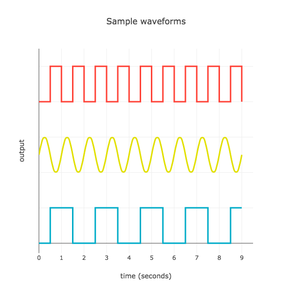
The graph shows how the output voltage depends on time. The Blinker creates a square wave because the voltage suddenly changes from high to low, creating right angles on the graph.
The bottom plot represents the signal you get directly from the battery. It constantly applies 9 volts to the LED output.
Try turning the dial on the Blinker clockwise. You’ll see the blinking rate slow down. We call this a low-frequency signal because there is a long time between the Blinker changing its state from high to low.
Finally, try turning the dial counterclockwise. The blinking speeds up a lot! This is a high-frequency signal.

Step Five
Frequency
We’ve used the word frequency a couple of times. This is defined as the number of times a signal pattern repeats itself every second. The units are called “per second” or Hertz (Hz).
For example, the wave shown in red above repeats itself one time every second. So the frequency is 1 per second, or 1 Hz.
Not all waves are square! The wave shown in yellow also has a frequency of 1 Hz. Do you see why?
Step Six
Out of Sync
Next let’s add another LED to the circuit to demonstrate another way the Blinker is used. By hooking up the LED between the VCC (or high voltage) foot and the output, the LED will be exactly out of sync with the green indicator light.
We give each these mode a name:
Active High: Current flows from OUTPUT to GND. The LED turns on when the output signal is high (on / 9V).
Active Low: Current flows from VCC to OUTPUT. The LED turns on when the output signal is low (off / 0V).
When the two modes are combined, the LEDs alternate their blinking.
Use the Circuit Stencil to add two extra pads for an LED module. Try extending the circuit and adding the extra LED in active low mode. The LEDs will flash back and forth!

Step Seven

Flashing lights in real life
Signals are not only for computer to computer communication. They are also often used for human communication, too!
When the light on your fire alarm starts to blink off and on you know there is trouble. Also skyscrapers have lights that flash to tell airplane pilots what sort of weather to expect. By adding flashing lights to your designs it is easy to communicate to the user some information without having to use words.
Note: The image is a public sculpture in London by artist Pierre Vivant
Step Eight
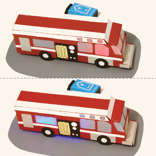
Design a Fire Truck
A place where flashing lights are seen regularly are on emergency vehicles. Instead of having the truck say “Please move out of the way, I’m coming through” the driver turns on their flashing lights to let everyone know they need to get out of the way.
In this step, turn your blinking light circuit into a firetruck project. You can use the attached template to cut out a fire truck or create your own design. Place it over the LED circuit, and flip the LEDs around so one flashes red and the other flashes blue.
Tip: use vellum or parchment paper in the firetruck windows to create a glowing lantern effect.

Step Nine
More flashing signals
Here are some additional ideas for Blinker module projects:
Add a buzzer in parallel with one of the lights so an alarm also goes off. Try adding a switch somewhere in the circuit so you can turn the flashing on and off. Take a look at the Flickering Jack-o-Lantern project to see how to make the circuit light-sensitive.