The world of electricity right at their fingertips!
Watch and learn with your child as they discover how electricity works through a series of fun and educational projects using our Circuit Scribe products. Coach your child through the project by using the provided tutorials instructions and soon they will be on their way to learning the basics of electricity!
Sound the Alarm!

Step One
Game Plan
https://edu.workbencheducation.com/cwists/preview/7451x
We want to make a system that creates noise when our item is taken. To create sound when an object is moved we can mix together a pressure sensor circuit with an inverter.
An inverter works by taking an input signal and outputting the opposite of that signal. In the case of our alarm design the signal is the pressure (or weight) of the object you want to keep secure. When the object is ON the pressure sensor the alarm (buzzer) is OFF. Once the object is removed or OFF the pressure sensor the alarm is activated turning ON the buzzer. Activating the buzzer when the item is removed from the sensor is exactly what we want for our system.
The two circuits needed to construct our alarm system are. . .
An Inverter Circuit
A Pressure Sensor
Step Two
Logic of the Inverter
Now that we know how the inverter works, lets learn how to create our own!
The inverter sounds complex but actually only requires three modules, a power source, an input (a switch in this case) and a transistor. Typically a transistor is used as a switch meaning when the transistor is activated electricity flows to your output (If you don't know what I'm talking about check out this tutorial). An inverter is the same concept except reversed. Electricity flows when the transistor is NOT activated (a.k.a why it is named a NOT gate). Achieving this is straight forward you simply place the output before the transistor instead of after. As you can see in the image the output wire is above the transistor. When the transistor is OFF the output is directly connected to the power source. When the transistor is ON the output is connected directly to ground.
When making the inverter in real life it is good practice to avoid the short circuit caused by connecting everything straight to ground. By adding a resistor before the output a short circuit condition is avoided and a clean 0V is output to the rest of your circuit.

Step Three
Circuit Scribe Inverter
Fortunately Circuit Scribe has all of the modules needed to make an inverter circuit. We are even able to test our design using the online circuit simulator!
Play around in the simulation and notice that when the switch is in the OFF state the LED is ON, and when the switch is in the ON state the LED is OFF.
Some of you might already be thinking ahead and noticing that we can replace the input switch with the pressure sensor. That's exactly what we are going to do!
Step Four
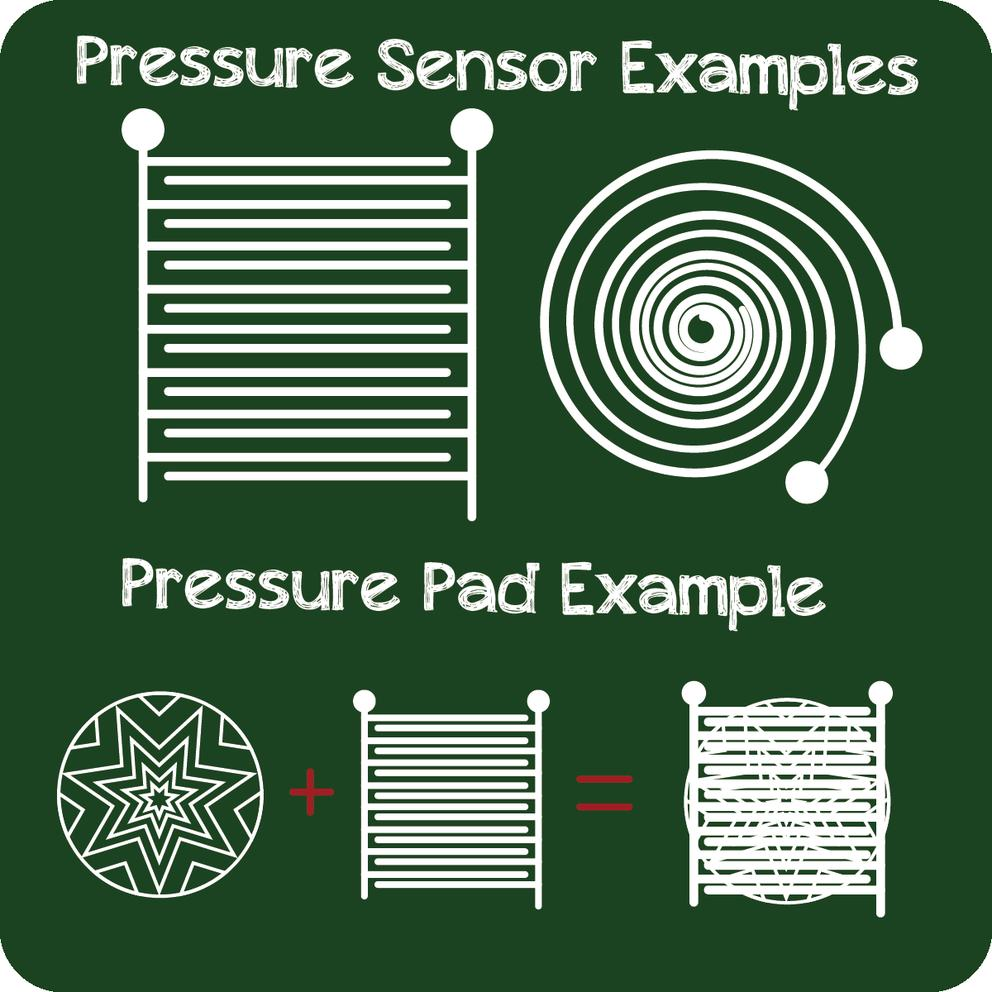
Pressure Sensor
The pressure sensor is one of the easiest and most fun circuits to make. It allows you to use unique and fun objects as inputs in your creations. Additionally the pressure pads are easy to customize!
The process to make a pressure sensor is two-fold. First draw two lines super close together but not allowing them to touch. Second draw a design on a separate piece of paper that bridges the two lines when placed on top. Refer to the image for ways to draw both your pressure sensor and pad. By applying some pressure to the pad the lines are bridged allowing electricity to flow. Viola you have your own fancy pressure sensor switch.
Check out the design we made, we used a mixture of the spiral and straight lines to create the sensor. Then we made a grapefruit pressure pad, which is both functional and healthy.
Don't be afraid to explore and have fun!

Step Five


Wire it up or. . . draw it up!
Now that we have the two parts to the design its time to finalize the layout.
Refer to the Virtual Sketch below to understand how the pressure sensor fits onto the inverter circuit.
Autodesk linkhttps://circuits.io/circuits/3648813-alarm-system
Replace the LED with the buzzer and you have a noise that will quickly grab your attention! For added effect put an LED in parallel with the buzzer.
You can now see what our final design looked like.
A PDF is attached for tracing if you want to get the project running quickly!
See if you can trick the alarm by removing the item and replacing it with another quickly. Indiana Jones Style!